Bedding a rifle is one of those procedures that makes you pucker your bum a little and just hope beyond hope you got everything right… The reality is the process is neither difficult or complicated, just fraught with consequence.
On the front side, it ends up being all about preparation, roughing the surfaces, masking off areas epoxy should not touch, laying out any tools or supplies that will be needed. Once the bedding epoxy is mixed you are on borrowed time, being well prepared ensures you can proceed calmly and meticulously.
On the back side, there are a couple of tools that make the whole thing sail quite smoothly. I would argue the tools topping the list are a good sharp wood chisel and a receiver heaver / action puller / bedding jack / whatever you want to call it.
Even though some form of receiver puller becomes a must-use tool for those that have used one if you do a bit of searching you quickly realize most people who bed a rifle don’t use one. They use some combination of whacking with a hammer, prying, hoping, and praying instead.
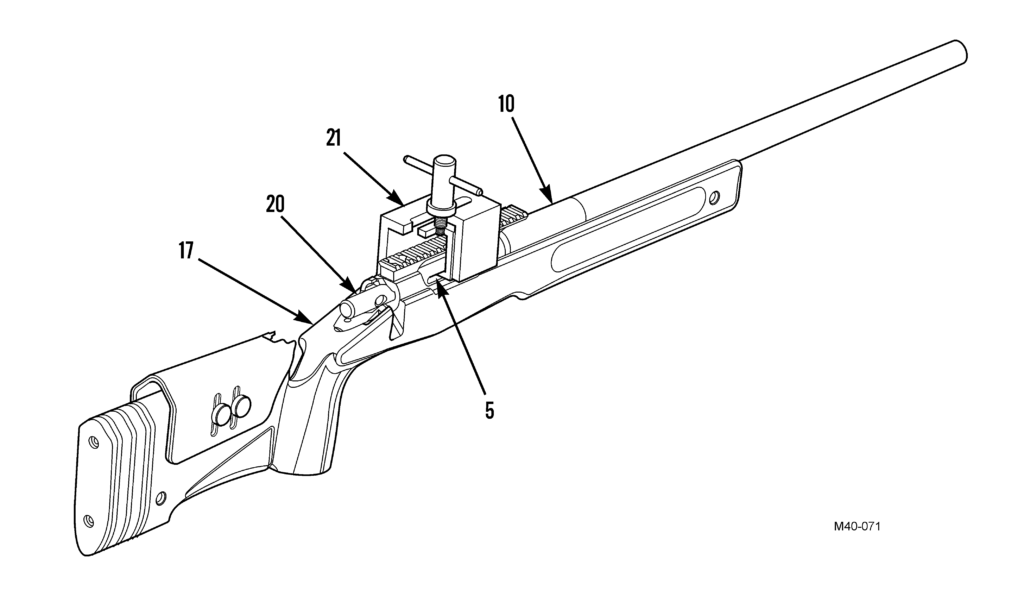
Building an action jack / receiver jack / bedding puller / (I’m sure I can come up with a few more combinations) is a pretty easy affair, often from scrap materials. I will detail a few different variations that can be found online here, along with links to the original sources. The first, obligatory, reference is to the US Marine Corps M40 Maintenance Manual. It shows a simple cutaway diagram of an “action puller” to be used when skim glassing.
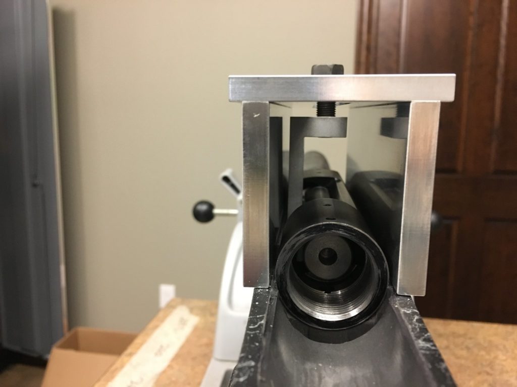
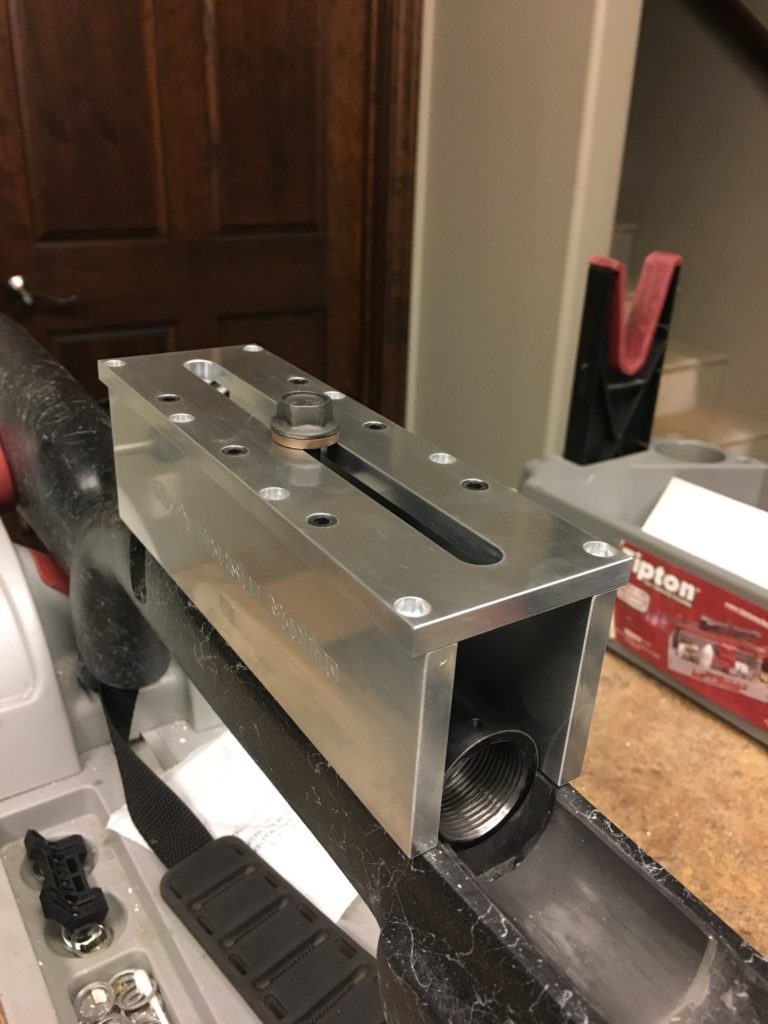
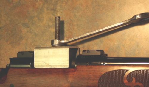
The next is the only commercially available “bedded action puller” that I could find as of the time of this writing. It is built by an outfit called Liberty Precision Machine and is based on the M40 unit, with a feature allowing the puller to be widened to accommodate receivers larger than 1.350″ OD.
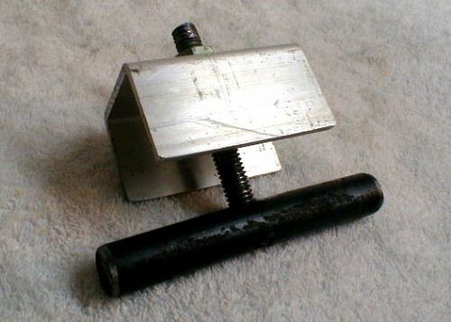
Next is a very similar unit just called an “action puller”, that was the source of a D.I.Y. article for RifleShooter.com. It is also seemingly based on the M40 puller design.
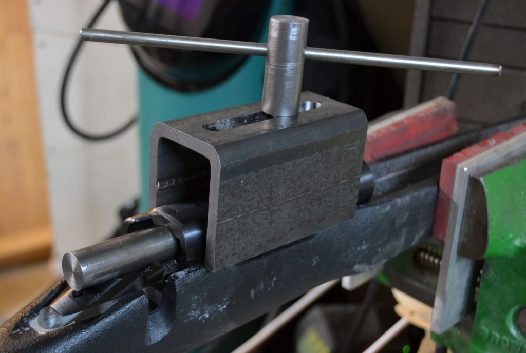
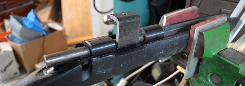
Next is an even more simple puller that is probably no less effective, this one from a post on weldingweb.com. This one also uses a cylinder that sits inside the receiver bore, but without the angled claw of the previous two. While simpler, this design would only work on receivers with an open ejection port design.
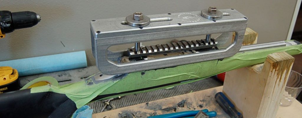
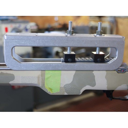
Finally, we have a couple of designs referred to as an “action jack”. These use a modified Picatinny rail or a Picatinny rail adapter to lift a receiver, instead of a rod placed inside the receiver. The first from LongRifles, Inc., and the second from Beanland Custom Rifles.
Any of these is a pretty easy project for someone with access to machine tools, and it would be easy enough to cobble something functional together with nothing more than a hacksaw and drill press. But how about another option? With the proliferation of 3d printers, how about a 3d printed “receiver heaver”? It’s probably a better use of that printer you dropped $300 on last Christmas than the 17 different cellphone stands you’ve printed so far.
This is as-yet untested, but I suppose it should work. Feedback / constructive criticism will be incorporated, and I will update this post and the linked files when I try out the design myself.
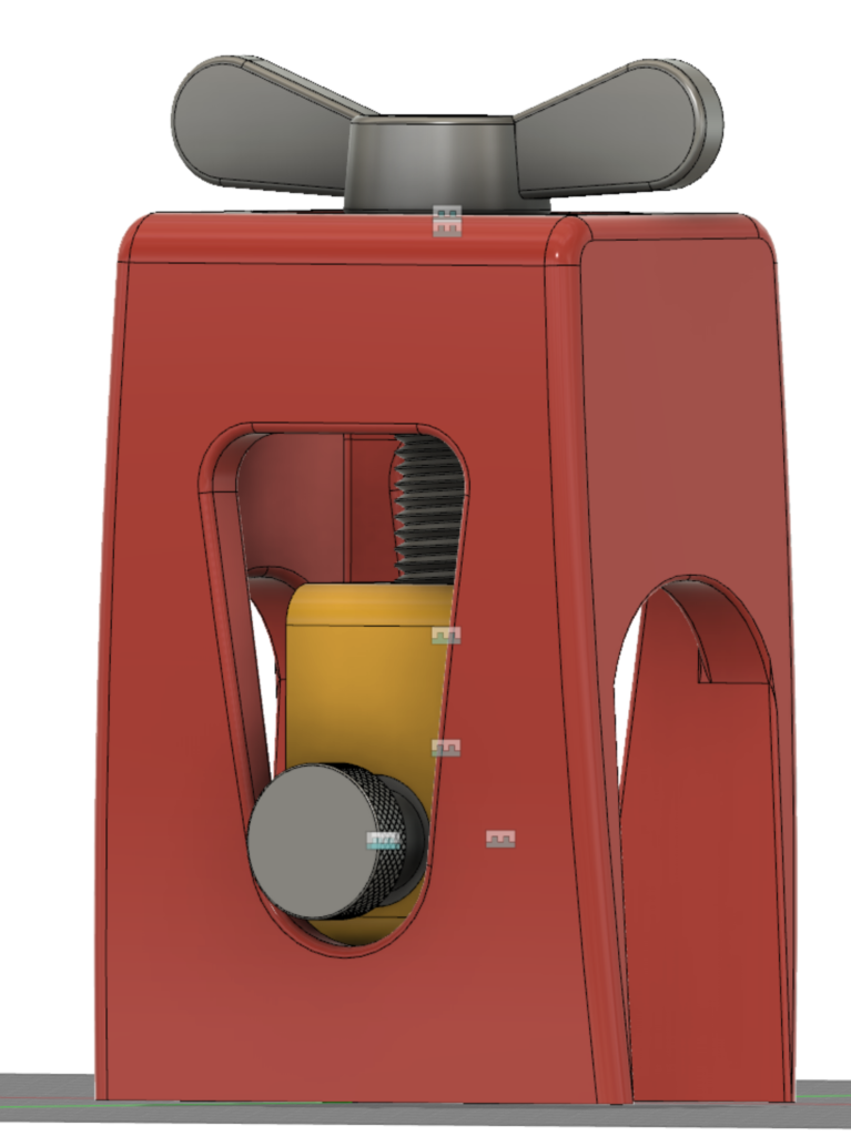
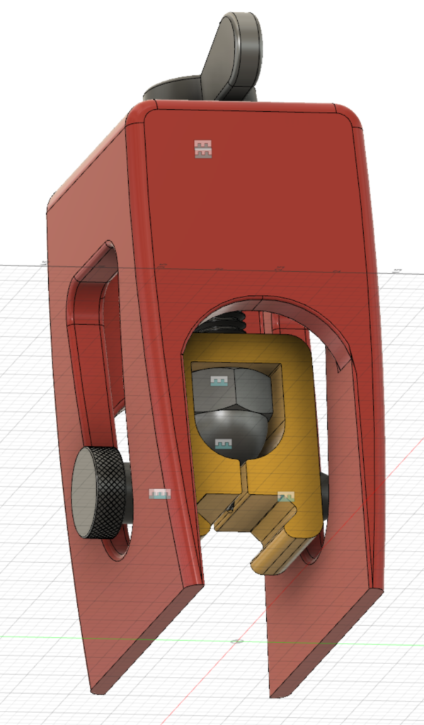
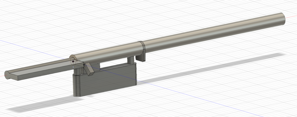
This heaver (puller) is smaller than most of the others you see above, it was intended to be able to fit inside the print volume of a small printer. I would recommend building two and pulling the receiver from directly above or behind the recoil lug. For stubborn removals or to ensure it was pulled perfectly square the second unit could be used toward the rear of the receiver. There is probably enough “flex” in the design to pull a fat body receiver.
The above zip archive contains the Fusion 360 source file (F3Z) as well as STL and STEP files of the two 3d printable parts. A full bill of materials is included for the parts used in the model from McMaster-Carr, although the BOM is pretty fancy-pants and one could be built much more modestly by visiting your local hardware store. Everything is designed around 1/4-20 and 1/2-13 thread sizes.
Print the Picatinny adapter (minor part) on one of the flat sides, and the major part upside down. Again, this is untested. As-is. No warranty. Your mileage may vary. Enjoy.
These parts can also be ordered printed starting from $20-30, check out the Order This Printed option on the Thingiverse listing.
Or, playing with Fusion 360’s Generative Design feature, which is available for free until January 2020!
I spend a fair portion of my every day at the office subtracting material from gun stocks to make receivers, barrels, and bottom metals fit. To be very clear, a firearm is a tool, a tool where the forces involved in the standard operation represent a hazardous condition if things aren’t right. More than that, they are a tool someone may bet life and limb on at some point.
Given the serious nature, and not discounting the fact I many times have 20 minutes to let my mind ponder these things while I watch a machine run, a great deal of thought goes into the forces at play and how my actions affect the structural integrity of the end result.
Autodesk has been spamming me non-stop about a free period of generative design in their Fusion 360 product and I decided it might be fun to validate a few assumptions about rifle stocks and play with Fusion 360 at the same time.
I probably should have spent a little time brushing up on long-forgotten basic physics before I began. Specifically, I should have made sure I had a good recall of the information required to make accurate inputs for the “Structural Loads” portion of the generative design. These loads are how the forces of recoil would be accurately interpreted by the analysis and enable it to generate something resembling an accurate output. I didn’t do that, I just pulled a few things that sounded semi-reasonable out of the air and ran with it. I will have to circle back on this.
For those not familiar with the construction of rifle stocks they are many and varied, but generally speaking, high-end stocks come in two forms outside of injection-molded stocks and “chassis” systems. There are wood stocks, in which the species of wood, the particular cut of wood, grain orientation, and etc. are all very pertinent to the structural integrity of the stock. Laminated wood is a bit different animal. Most of the stocks I deal with day to day, though, are of the composite variety. They are constructed of a fiberglass or carbon fiber shell filled with a “fill” material. The shell on these stocks is exactly what you would expect of a fiberglass or carbon fiber part, they are various layers of cloth material molded into the appropriate shape. Typical shell thickness ranges from 0.025″ to 0.125″, largely depending on fabric type, the brand of stock, location on the stock. This otherwise hollow shell is stuffed full of a combination of epoxy and a variety of other filler materials, most commonly little pieces of chopped or milled fiberglass or silica.
You can clearly distinguish the thin carbon fiber shell, two different types of fill material, and stainless steel pillars in this photo of a Manners elite carbon fiber stock
The assumption typically made is the strength and overall structural integrity of a composite stock is largely in the shell. The fill is typically there to support the various features and accessories, such as the recoil lug area forward of the receiver, sling studs or flush cups attached for carrying, etc. Ok, cool, seems reasonable. Except, when we install a barreled action, bottom metal, and everything else into a stock to make a complete rifle, we tend to gut the thing. The entire top gets hogged out, almost to the edges, for the receiver. Likewise, underneath the receiver, most of the bottom gets hogged out for the bottom metal. Most of what is left of the shell are the two sides of the stock, which doesn’t seem to lend as much structural integrity as one would like… Especially directly rearward of where the recoil gets absorbed into the stock.
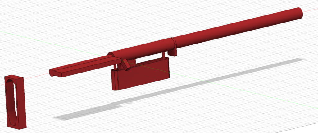
I wasn’t intending to be very scientific, I was just hoping to start getting an idea of how the forces are transmitted through the stock. So here we go — to start, I modeled up an extremely simplistic representation of a barreled action. The bolt and bolt handle was modeled in very simple form both closed and fully open.
Extremely simple barreled action
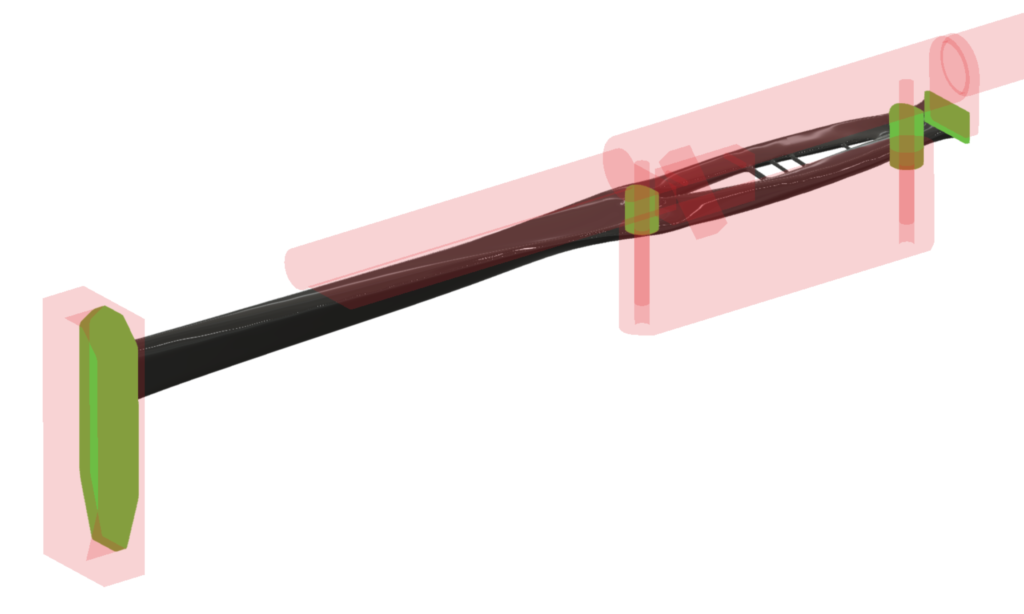
This generative design functionality in Fusion 360 requires 3 major elements. You must define all of your required features, in our case things such as where the recoil lug will transmit force into the stock, and where the recoil pad will attach / where the stock will transmit force into your shoulder. Fusion refers to these features as “Preserve Geometry”. You must also define your “Obstacle Geometry”, these are all the places you don’t want the software to put any material. In our case, we have a receiver, recoil lug, bolt, bolt handle, barrel, bottom metal, trigger, etc. We don’t want the software to create structural elements of our stock that can’t actually exist, because another component of the rifle has to live there.
Fusion 360 Generative Design “Obstacle Geometry”
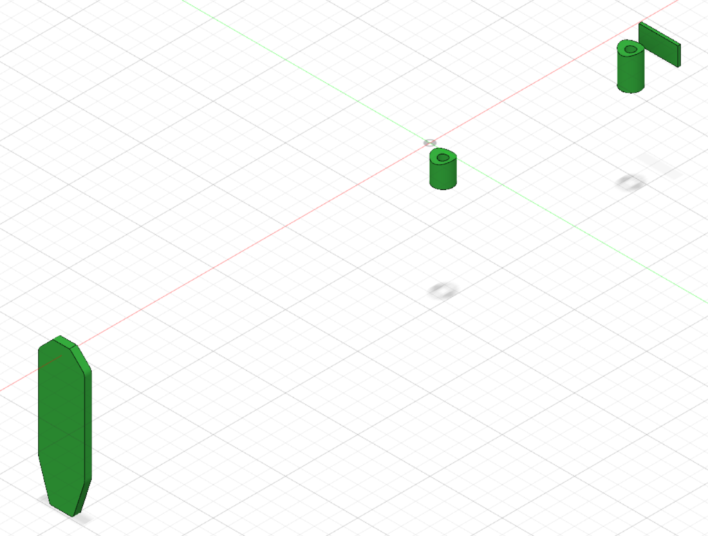
I created only four features the software was asked to preserve, the rear of the recoil lug well, the recoil pad attachment face, and two pillars with lengths typical of an M5 short action DBM.
Fusion 360 Generative Design “Preserve Geometry”
Loads must also be defined. The force of gravity is pre-defined for you by the software, but it can be nuked or modified if necessary. This is probably one of the more critical parts of the whole deal, garbage in – garbage out, as they say. Accurately defining the loads your part/object will be subject to will allow the software to generate a model able to withstand those loads. Not accurately defining these constraints will put you out in left field, guessing — but today I ignored this fact I already knew and think I learned a few things anyway, TBD.
I also ignored any form or fashion of stock “user interface”. In theory, once this design is generated, you could install a barreled action and bottom metal, pull it to your shoulder, and fire it. Doing so would be a bit of a trick, however, as there are zero provisions for actually holding onto this generated stock, nowhere to rest your cheek, none of what makes a stock — well, a stock. A stock really has two jobs, it has to hold onto the receiver and all the other components, and deal with all the forces that happen when fired. The stock also has to serve as a comfortable and intuitive user interface, allowing one to use the firearm effectively. Yes, we are absolutely ignoring that second one, to be continued…
Fusion will also allow you to constrain your simulation to particular materials and production methods. My general sense is the materials are accurately simulated at least for parts that will ultimately be machined, perhaps not created additively, such as with 3d printing. I also have the impression the various options related to how the part will be produced is somewhat hand-wavy. At least in my experience thus far it seems dubious to think you might actually end up with a part you can turn around and produce using this method. You will be money ahead if you simply use it as a means of idea generation.
I ran the generation process with a variety of materials and production methods, but I will only be sharing the results of the CFRP (Carbon Fiber Reinforced Polymer) material. CFRP adequately describes the construction of a composite stock, but considering a stock is a shell with fill I will be taking any output with an additional grain of salt (or in the case of Fusion, adding in some additional “Safety Factor”).
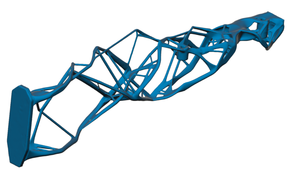
I ultimately ran two different simulations with different loads and settings. One a bit on the side of having this big piece of thing that needs to carry a barreled action around, but doesn’t necessarily need to withstand much recoil. There are a variety of settings related to the design objective at your disposal in this process. For the first simulation, with low recoil loading, it was directed to maximize stiffness at low target weight.
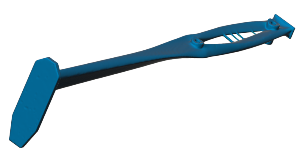
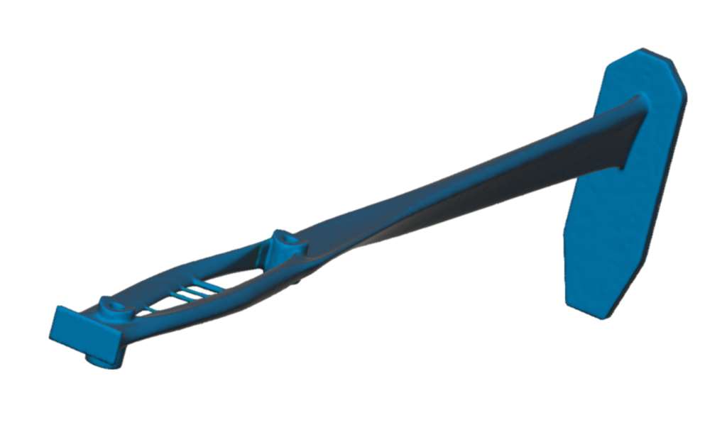
As you can see from the images below, the generative design process resulted in a stock a bit exoskeletal in nature, for lack of a better term. You can imagine this trellis-like structure would result in an overall part that was fairly stiff at a low weight — around 200 grams in this case.
Simulation 1 with Preserve and Obstacle GeometrySimulation 1 rear viewSimulation 1 front view
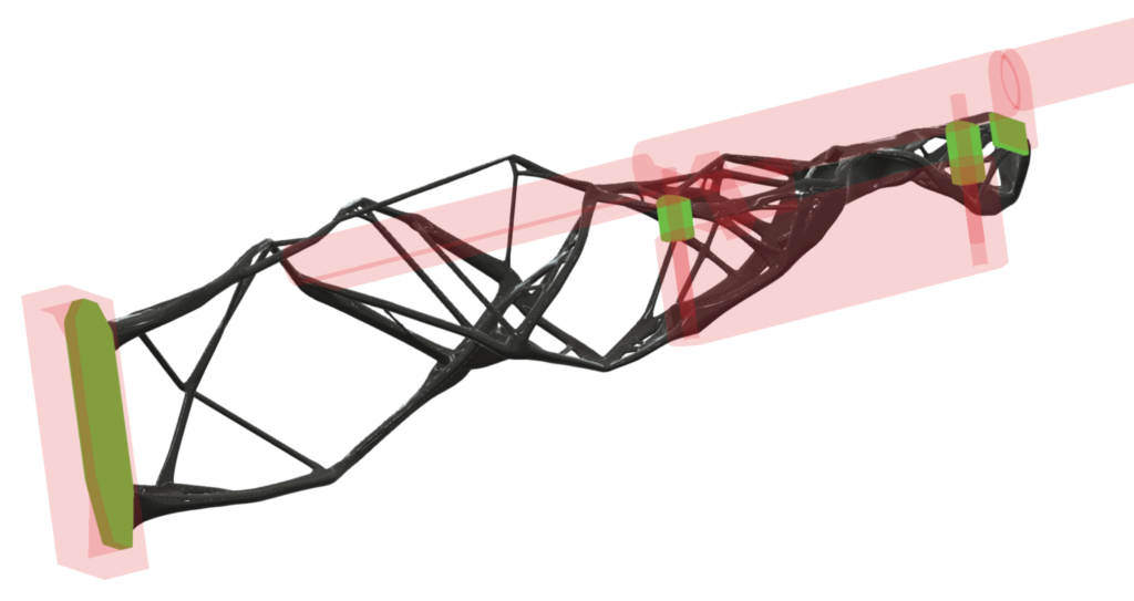
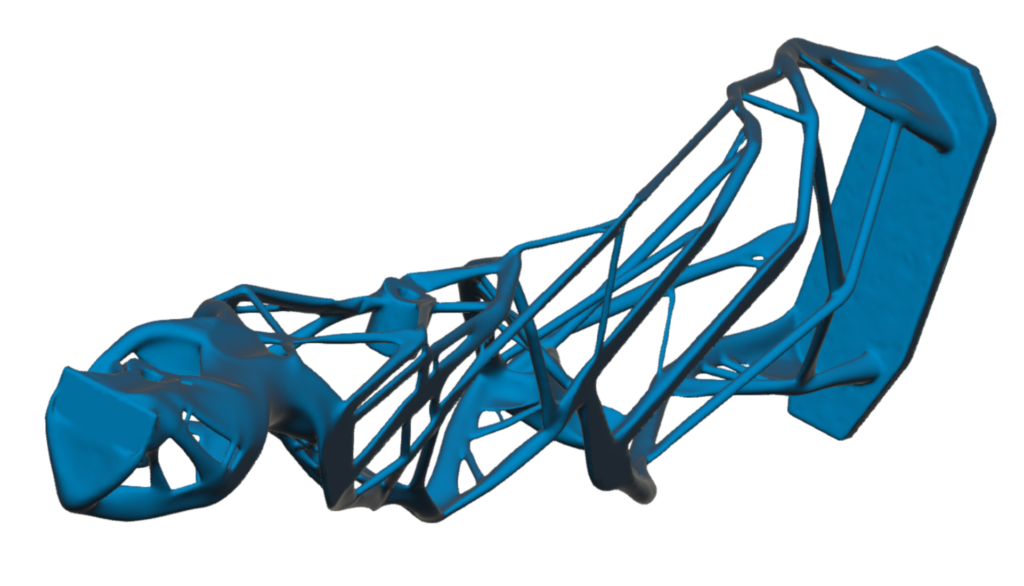
The other simulation was performed as if the stock was going to have to eat a ton of punishment coming through the recoil lug area. The objectives for this simulation were a bit in opposition to the previous one. It was instructed to minimize mass while handling the specified forces, with a defined safety factor.
As you can see in the following images of the result, this design was very simple and architectural. The generative process resulted in what looks to be as close as it could come to a linear beam between the lug face and the recoil pad. This thing would very likely eat recoil quite well, but might also be a bit of a wet noodle to handle — but also at around 200 grams.
Simulation 2 with Preserve and Obstacle GeometrySimulation 2 rear viewSimulation 2 front view
What’s the take-away? I have some thoughts, but I’m not sure these particular simulations spell out any sort of improved stock design on their own. You can grab my working file below if playing with this sounds like a lovely way to spend an afternoon!
After a bit more time playing with generative design, it might be fun to bring things full circle by modeling a good representation of a “real” stock and playing with Fusion 360’s simulation tools. It would be interesting to see, with different material types applied, what manner of interaction there is between the shell and the fill material.
To be continued, just so long as I don’t get distracted by too many shiny objects.